Quick reference for the NadHAT board
Presentation of the board :
The NadHAT PYBF405 board is a redesigned PYBV11 board compatible with the uHAT form factor. That does not mean you need a Raspberry Pi board to make it run, even if it’s can be useful for special purposes. It purpose is to make run a wide selection of uHAT or pHAT extension boards at a fraction of power of any Raspberry Pi model.
Below is the NadHAT PYBF405 board side by side with the PYBV11 board.
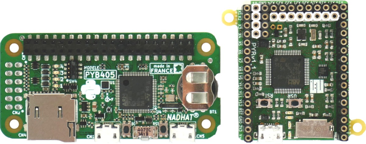
NadHAT PYBF405 board is bigger than PYBV11 board. Its size is 32x67mm (21cm2) where the PYBV11 is only 33x42mm (14cm2), for an increase of fifty percent.
Features introduced by the board :
- This amount of space allow to improve the design with :
- full format push-push micro-sd connector,
- accelerometer position at the center of the board,
- lithium coin cell battery holder to timekeep RTC when power is lost,
- 2nd micro-USB connector for power supply (computer USB cable removed w/o power loss),
- dedicated button to enter DFU mode,
- four 0-16V analog to digital protected inputs,
- four 50V 100mA open collector outputs with protection diode for inductive load (relays),
- side user switch button that allow to be pressed even with a plastic enclosure,
- convenient passtrough connector for stackup design,
- compatible in almost cases with Raspberry Pi’s uHAT or pHAT.
Connectors, buttons and jumper of the board :
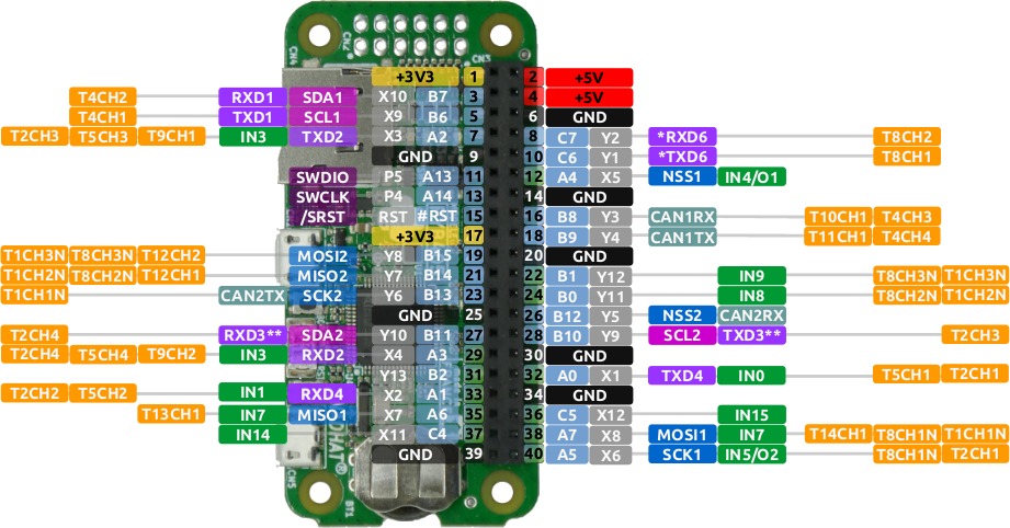
CN3 : 40 pins Raspberry Pi legacy pinout
CN2 : 12 pins 4x analog IN 4x open collector OUT
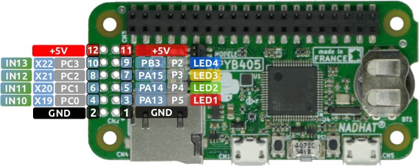
X19, X20, X21, and X22 are analogs inputs. A voltage divider of 5.545455 is applied on each entry. Vref of ADC is 3.3V. 1 LSB is so equal to ((3.3/4095)*5.545455) = 4.469 mV. On the other hand, the full range is 4,469e-3*4095 = 18.3V
P2, P3, P4, P5 are digital output buffered with a BC856 transistor.
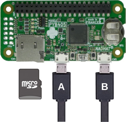
MicroSD and micro-usb (x2) connectors
SW4 Raspberry Pi UART1 legacy serial port configuration
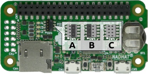
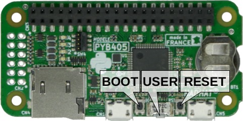
Boot, Reset and User buttons
Below is a quick reference for the NadHAT board. If it is your first time working with this board please consider reading the following sections first:
General board control
See pyb.
import pyb

pyb.repl_uart(pyb.UART(1, 9600)) # duplicate REPL on UART(1)
pyb.wfi() # pause CPU, waiting for interrupt
pyb.freq() # get CPU and bus frequencies
pyb.freq(60000000) # set CPU freq to 60MHz
pyb.stop() # stop CPU, waiting for external interrupt
Delay and timing
Use the time module:
import time

time.sleep(1)           # sleep for 1 second
time.sleep_ms(500)      # sleep for 500 milliseconds
time.sleep_us(10)       # sleep for 10 microseconds
start = time.ticks_ms() # get value of millisecond counter
delta = time.ticks_diff(time.ticks_ms(), start) # compute time difference
Internal LEDs
See pyb.LED.
from pyb import LED

led = LED(1) # 1=red, 2=green, 3=yellow, 4=blue
led.toggle()
led.on()
led.off()

# LEDs 3 and 4 support PWM intensity (0-255)
LED(4).intensity()    # get intensity
LED(4).intensity(128) # set intensity to half
Internal switch
See pyb.Switch.
from pyb import Switch

sw = Switch()
sw.value() # returns True or False
sw.callback(lambda: pyb.LED(1).toggle())
Pins and GPIO
See pyb.Pin.
from pyb import Pin

p_out = Pin('X1', Pin.OUT_PP)
p_out.high()
p_out.low()

p_in = Pin('X2', Pin.IN, Pin.PULL_UP)
p_in.value() # get value, 0 or 1
Servo control
See pyb.Servo.
from pyb import Servo

s1 = Servo(1) # servo on position 1 (X1, VIN, GND)
s1.angle(45) # move to 45 degrees
s1.angle(-60, 1500) # move to -60 degrees in 1500ms
s1.speed(50) # for continuous rotation servos
External interrupts
See pyb.ExtInt.
from pyb import Pin, ExtInt

callback = lambda e: print("intr")
ext = ExtInt(Pin('Y1'), ExtInt.IRQ_RISING, Pin.PULL_NONE, callback)
Timers
See pyb.Timer.
from pyb import Timer

tim = Timer(1, freq=1000)
tim.counter() # get counter value
tim.freq(0.5) # 0.5 Hz
tim.callback(lambda t: pyb.LED(1).toggle())
RTC (real time clock)
See pyb.RTC
from pyb import RTC

rtc = RTC()
rtc.datetime((2017, 8, 23, 1, 12, 48, 0, 0)) # set a specific date and time
rtc.datetime() # get date and time
PWM (pulse width modulation)
from pyb import Pin, Timer

p = Pin('X1') # X1 has TIM2, CH1
tim = Timer(2, freq=1000)
ch = tim.channel(1, Timer.PWM, pin=p)
ch.pulse_width_percent(50)
ADC (analog to digital conversion)
from pyb import Pin, ADC

adc = ADC(Pin('X19'))
adc.read() # read value, 0-4095
DAC (digital to analog conversion)
from pyb import Pin, DAC

dac = DAC(Pin('X5'))
dac.write(120) # output between 0 and 255
UART (serial bus)
See pyb.UART.
from pyb import UART

uart = UART(1, 9600)
uart.write('hello')
uart.read(5) # read up to 5 bytes
SPI bus
See pyb.SPI.
from pyb import SPI

spi = SPI(1, SPI.MASTER, baudrate=200000, polarity=1, phase=0)
spi.send('hello')
spi.recv(5) # receive 5 bytes on the bus
spi.send_recv('hello') # send and receive 5 bytes
I2C bus
Hardware I2C is available on the X and Y halves of the NadHAT board via I2C('X')
and I2C('Y'). Alternatively pass in the integer identifier of the peripheral,
eg I2C(1). Software I2C is also available by explicitly specifying the
scl and sda pins instead of the bus name. For more details see
machine.I2C.
from machine import I2C

i2c = I2C('X', freq=400000)                 # create hardware I2c object
i2c = I2C(scl='X1', sda='X2', freq=100000)  # create software I2C object

i2c.scan()                          # returns list of slave addresses
i2c.writeto(0x42, 'hello')          # write 5 bytes to slave with address 0x42
i2c.readfrom(0x42, 5)               # read 5 bytes from slave

i2c.readfrom_mem(0x42, 0x10, 2)     # read 2 bytes from slave 0x42, slave memory 0x10
i2c.writeto_mem(0x42, 0x10, 'xy')   # write 2 bytes to slave 0x42, slave memory 0x10
Note: for legacy I2C support see pyb.I2C.